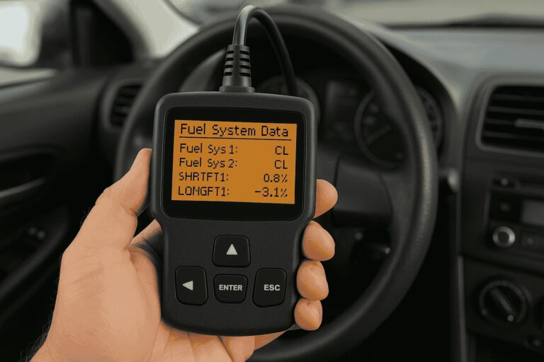
Plug an OBD2 scanner into your car and you will get a screen full of codes, acronyms, and status readings that look like they were written for an aerospace engineer. For most drivers, it is a frustrating wall of confusing terminology. One of the most commonly misunderstood readings is Fuel SYS 1 CL.
Here is the thing: this one is actually not as complicated as it looks. Once you understand what the scanner is telling you, the path forward becomes pretty clear. This guide breaks it all down in plain language, walks you through what causes the issue, and shows you exactly what to do about it.
Table of Contents
What Does Fuel SYS 1 CL Actually Mean?
When your scanner displays Fuel SYS 1 CL, it is telling you that fuel injector Bank 1 is currently operating in closed loop mode. That is it. That is what the abbreviation stands for. “SYS 1” refers to Bank 1 of the fuel system, and “CL” stands for Closed Loop.
Now, here is where it gets interesting. Closed loop is not inherently a problem. It is actually the mode your engine is supposed to run in under normal operating conditions. But when Bank 1 is sitting in closed loop while Bank 2 is doing something different, or when closed loop is displaying alongside a fault condition, that is when you need to pay attention.
To understand why, you need to know the difference between open loop and closed loop, and why your engine switches between the two.
Open Loop vs. Closed Loop: The Two Modes Your Engine Lives In
Think of your engine’s fuel management system as having two personalities. One is cautious and data-driven. The other follows a preset script without checking real-world feedback.
Open loop is the preset script mode. When your engine runs in open loop, the ECU (Engine Control Unit) injects fuel based on a pre-programmed fuel map. It does not consult sensor feedback. It just follows instructions. This happens during cold starts, hard acceleration, and deceleration because those are situations where the sensor data cannot be fully trusted or where split-second fuel delivery is more important than precision.
Closed loop is the smart, feedback-driven mode. Once the engine warms up and everything is operating within normal parameters, the ECU switches to closed loop. In this mode, it actively reads the oxygen sensor output and uses that data to fine-tune the air-to-fuel ratio in real time. We are talking about adjustments happening multiple times per second. It is a constant loop of measure, adjust, measure again, adjust again.
The oxygen sensor, sometimes called the lambda sensor, is the key player here. It sits in the exhaust stream and measures the oxygen content of the exhaust gases. Too much oxygen means the mixture is running lean (not enough fuel). Too little oxygen means it is running rich (too much fuel). The ECU reads that data and responds accordingly, either adding more fuel or pulling back on it to keep everything balanced.
This constant adjustment is what makes closed loop mode so efficient. Your engine delivers better fuel economy, lower emissions, and smoother performance when operating in a healthy closed loop compared to running on a static fuel map.
What Bank 1 Actually Refers To
On a four-cylinder engine, there is essentially one bank. Bank 1 is the entire engine. On V6 and V8 engines, the engine is split into two banks. Bank 1 is the side of the engine that contains cylinder number one. Bank 2 is the opposite side.
Each bank has its own oxygen sensors, one upstream (before the catalytic converter) and one downstream (after it). The upstream sensor, Bank 1 Sensor 1, is the one that drives the closed loop fuel correction. The downstream sensor primarily monitors catalytic converter efficiency.
So when the scanner shows Fuel SYS 1 CL, it is specifically telling you about the operating state of the Bank 1 fuel circuit. If you also see Fuel SYS 2 on a multi-cylinder engine, that is the Bank 2 reading. Seeing “N/A” next to Fuel SYS 2 on a four-cylinder engine is completely normal because there is no Bank 2 on a straight-four engine.
When Fuel SYS 1 CL Is Normal (and When It Is Not)
This is where a lot of drivers get confused, because seeing “CL” on the scanner does not automatically mean something is wrong. Context matters.
In a healthy, warmed-up engine running at a steady throttle with low RPM fluctuation, Fuel SYS 1 CL is exactly what you want to see. The system is working as designed. The ECU is reading the oxygen sensor and making real-time fuel adjustments. That is normal operation.
But here are the situations where seeing this reading should make you dig deeper:
- Bank 1 shows CL but Bank 2 shows OL (open loop) when both should match. If one bank is operating in a completely different mode from the other on a multi-bank engine, something is wrong on one side. This asymmetry is a red flag.
- The engine is running noticeably rich and the scanner shows CL. This combination often means the oxygen sensor is providing bad data. The ECU thinks it is making corrections in closed loop, but it is actually getting faulty readings and overcorrecting in the wrong direction.
- CL appears alongside a fault code. If the scanner is throwing diagnostic trouble codes alongside the CL status, something in the feedback loop is broken. The CL reading alone is not the story. The accompanying codes tell you what is actually failing.
- The engine shows CL on a cold start. A normal engine starts in open loop and transitions to closed loop only after warming up, typically within two to five minutes. If the scanner shows CL immediately at cold start, the ECU may be receiving a false temperature reading or the coolant temperature sensor may have failed.
What Is a CL Fault and Why Does It Happen?
A CL fault in the fuel system context means the closed loop system has encountered a condition it cannot properly manage. The ECU was supposed to be using oxygen sensor feedback to regulate fuel delivery, but something in that feedback chain has broken down.
When the fault occurs, the ECU loses its ability to trust the oxygen sensor data. Without reliable feedback, the whole point of closed loop operation is gone. The system may limp along on estimated values, or it may throw a fault code and revert behaviors that cause drivability problems.
Several things can cause this to happen. Here are the most common culprits:
1. Faulty or Degraded Oxygen Sensor
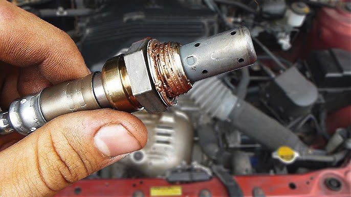
This is the single most common cause of a closed loop fault. The oxygen sensor is the entire foundation of closed loop operation. When it fails, goes lazy (meaning it responds too slowly), gets contaminated with oil or coolant, or simply reaches the end of its service life, the data it sends to the ECU becomes unreliable.
A slow or failing O2 sensor often produces a voltage output that is stuck at a fixed level rather than fluctuating as it should in normal operation. In closed loop, the Bank 1 Sensor 1 voltage should be switching rapidly between roughly 0.1 and 0.9 volts. A sensor stuck at 0.000 volts, or stuck at a fixed mid-range value, is a dead sensor or a wiring problem.
This is exactly what the live data table below illustrates. Notice how Bank 1 Sensor 1 reads 0.000 while the other sensors are reading in the expected range:
| Sensor Location | Live Data Reading | Status |
|---|---|---|
| Bank 2 Sensor 1 | 0.500 to 0.750 | Normal fluctuation |
| Bank 2 Sensor 2 | 0.500 to 0.750 | Normal fluctuation |
| Bank 1 Sensor 2 | 0.500 to 0.750 | Normal fluctuation |
| Bank 1 Sensor 1 | 0.000 | No signal – likely failed |
When Bank 1 Sensor 1 reads a flat 0.000 volts, it is not fluctuating. It is not doing anything. The ECU has no usable feedback from that sensor, which means it cannot properly manage closed loop fuel delivery on Bank 1. Hence the fault.
2. Damaged Wiring or Corroded Connectors
The oxygen sensor itself might be perfectly fine. But if the wiring between the sensor and the ECM is damaged, frayed, corroded at the connector, or has a broken ground circuit, the ECU receives the same result: no signal or a corrupted signal.
Wiring problems are especially sneaky because a damaged wire can still make intermittent contact. The sensor might read correctly some of the time and fail other times, which causes the fault to appear and disappear inconsistently. That pattern is actually a useful diagnostic clue. Intermittent faults that come and go often point toward a connection or wiring issue rather than a completely dead component.
Ground connections deserve special attention. If the engine ground or the sensor ground is corroded or loose, the sensor circuit cannot complete properly. Always check ground connections when chasing electrical faults before replacing sensors.
3. Carbon Buildup and Contamination
On high-mileage engines, the oxygen sensor can become coated with carbon deposits, phosphorus from oil consumption, or silicone contamination from certain types of sealants used during previous repairs. Any of these coatings insulate the sensor’s detecting element and slow its response time.
A contaminated sensor may not throw a hard fault code immediately. Instead, it gradually becomes lazier in its response until the ECU determines the readings are no longer reliable enough for closed loop operation. At that point, the CL fault appears.
4. Vacuum Leaks
A vacuum leak lets unmetered air into the intake manifold past the mass airflow sensor. The ECU does not know this extra air exists because it was never measured. So it injects the fuel amount appropriate for the air it thinks is entering, while in reality the engine is running lean from all the unmeasured air slipping in through the leak.
The oxygen sensor picks up on this lean condition and tells the ECU to add more fuel. The ECU adds fuel. The sensor detects slightly less lean. The ECU adds a bit more. Eventually the fuel trim corrections max out at the limits of what the ECU is allowed to adjust, and the system can no longer maintain proper closed loop operation. A CL fault can follow.
Vacuum leaks are particularly common after engine work. Any time an intake manifold gasket, throttle body gasket, vacuum hose, or intake boot is disturbed during a repair, there is potential for a leak to develop if everything is not properly reseated and torqued.
5. Bad Spark Plugs, Wires, or Ignition Coils
This one surprises people. How does ignition have anything to do with the fuel system’s closed loop status?
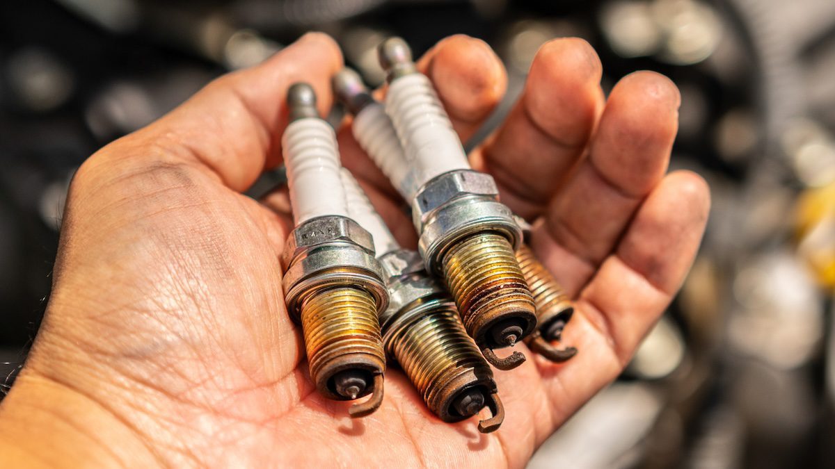
When a spark plug is fouled or misfiring, the fuel-air mixture in that cylinder does not fully combust. Unburned fuel and oxygen pass through to the exhaust. The downstream oxygen sensor picks up unusually high oxygen content and signals the ECU that the mixture is running lean, triggering more fuel injection. If the misfire is frequent enough, it disrupts the closed loop fuel correction process significantly.
Worn spark plug wires can cause similar problems through voltage leakage, causing weak sparks and partial combustion. A failing ignition coil that causes a cylinder to misfire intermittently can produce the same downstream oxygen sensor confusion.
If you recently replaced spark plugs, wires, ignition coils, or other ignition components and the CL fault appeared shortly afterward, incorrect installation or a wrong part specification is worth investigating before assuming a sensor failure.
6. Repairs That Changed Settings or Introduced New Variables
Sometimes a CL fault appears not because something broke, but because something was changed and the system has not been properly recalibrated. Specific repairs and replacements can trigger this if not done correctly:
- Replacing spark plugs or spark plug wires with incorrect specifications
- Replacing all four oxygen or lambda sensors at once without clearing adaptation values
- Changing the distributor without resetting timing
- Repairing or replacing vacuum lines and leaving small air gaps
- Replacing the throttle body gasket, valve cover gasket, or intake manifold gasket without proper torque sequence
- Failing to reset the throttle position sensor to zero percent at idle after throttle body service
These repair-related causes are worth knowing because they save you from chasing a phantom fault. If you just had work done on any of these components and the Fuel SYS 1 CL fault appeared afterward, start your investigation right there instead of immediately assuming the O2 sensor has failed independently.
How to Diagnose the Actual Cause Step by Step
Knowing the possible causes is only useful if you have a logical way to narrow down which one is actually affecting your vehicle. Here is how to approach the diagnosis systematically without wasting money replacing parts that do not need replacing.
Step 1: Pull All Codes, Not Just the Status Reading
The Fuel SYS 1 CL display is a status reading, not a diagnostic trouble code. It tells you what mode the fuel system is in, but it does not by itself tell you what is wrong. Your first job is to pull every stored code from the ECU and write them all down.
Look specifically for codes in the P0130 to P0167 range, which cover oxygen sensor circuit faults, and P0170 to P0175, which cover fuel trim faults. These codes will tell you a much more specific story than the status reading alone.
Step 2: Use Live Data to Watch the Oxygen Sensor in Real Time
A short scan might not tell you much. Run a longer scan while the engine is at operating temperature and watch the oxygen sensor voltage live. Here is what you are looking for:
- In closed loop, Bank 1 Sensor 1 should be fluctuating rapidly between approximately 0.1 and 0.9 volts. That rapid switching is the sensor doing its job.
- A sensor stuck at 0.000 volts has no signal. Either the sensor is dead or there is a wiring break.
- A sensor stuck at a fixed voltage like 0.450 volts is not switching. It may be contaminated, lazy, or failing.
- A sensor that moves slowly and infrequently is a lazy sensor nearing the end of its service life.
Watch the fuel trim values at the same time. Short-term fuel trim (STFT) and long-term fuel trim (LTFT) tell you whether the ECU is adding or removing fuel to compensate for something. Large positive trim values mean the engine is running lean and the ECU is trying to add fuel. Large negative values mean it is running rich. Either extreme points toward a problem the ECU cannot self-correct.
Step 3: Do a Visual Inspection Before Replacing Anything
Pop the hood and spend five minutes looking before you spend money. Check for:
- Cracked, disconnected, or collapsed vacuum hoses
- Damaged wiring near the oxygen sensor or along the sensor harness route
- Corroded connector pins on the oxygen sensor plug
- Any oily residue inside the intake tube or air filter housing (indicating a PCV problem that could contaminate the O2 sensor)
- Signs of any recent repair work that might have disturbed related components
Visual inspection catches the easy wins. A disconnected vacuum hose takes 30 seconds to fix. A corroded connector can often be cleaned with electrical contact cleaner and fixed without buying a single part. Always look before you spend.
Step 4: Test the Sensor Circuit With a Multimeter
If the live data shows a problem with Bank 1 Sensor 1 but the visual inspection looks clean, the next step is testing the circuit itself. A multimeter lets you check whether the sensor is receiving power, whether the ground is complete, and whether the signal wire is carrying a voltage signal.
Your vehicle’s repair manual will give you the specific test procedures and expected values for your make and model. If you do not have the manual, manufacturer-specific forums for your vehicle are usually an excellent resource for pinout information and test procedures.
How to Replace the Bank 1 Sensor 1 Oxygen Sensor
If diagnosis confirms the oxygen sensor is the problem, replacement is one of the more accessible DIY repairs you can do. The following steps work on most four-cylinder vehicles. This example uses a 2004 Kia Spectra as the reference vehicle, but the basic process applies across most makes and models with minor variations.
What You Will Need
- Replacement oxygen sensor (Bank 1 Sensor 1, specific to your vehicle)
- O2 sensor socket (a specialty socket with a wire slot cut into the side)
- Ratchet and extension
- Penetrating oil (PB Blaster or similar)
- Anti-seize compound
- OBD2 scanner to clear codes after the repair
Step-by-Step Replacement Process
- Let the exhaust cool down. If you have been driving, give it at least an hour. Exhaust components get extremely hot and will burn you badly if you rush this step.
- Locate Bank 1 Sensor 1. Open the hood and trace back from the first cylinder. On a four-cylinder engine, the upstream oxygen sensor is located on the exhaust manifold or in the downpipe, ahead of the catalytic converter. You will see it threaded into the exhaust pipe with a wiring harness running from it.
- Disconnect the wiring harness. There is a small tab or clip on the connector. Press it in and pull the connector apart. Do not yank on the wires themselves.
- Apply penetrating oil. Spray PB Blaster or a similar penetrating lubricant around the base of the sensor where it threads into the exhaust pipe. Let it soak for at least 10 to 15 minutes. Oxygen sensors that have been in place for years can be extremely tight due to heat and corrosion. Skipping this step is how you end up snapping the sensor off in the bung.
- Slide the O2 sensor socket over the sensor. The slot in the side of the socket allows the wire to pass through. Push the socket down over the sensor body until it seats properly.
- Attach your ratchet and loosen the sensor. Turn counterclockwise to loosen. If it is very tight, a breaker bar gives you better leverage than a standard ratchet. Do not use excessive force without patience. Work it back and forth slightly if needed.
- Remove the old sensor. Once loose, unthread it by hand the rest of the way and pull it out.
- Apply anti-seize to the new sensor threads. This is important. Anti-seize compound prevents the new sensor from galling or seizing into the bung, which makes future removal much easier. Apply a small amount to the threads, being careful not to get any on the sensing element tip.
- Thread the new sensor in by hand first. This prevents cross-threading, which would damage the bung and create a much bigger problem.
- Tighten to specification. Use your ratchet and O2 sensor socket to tighten the sensor to the torque specification in your repair manual. Typically around 30 to 44 foot-pounds, but always verify for your specific vehicle.
- Reconnect the wiring harness. Push the connector together until it clicks and seats firmly.
- Clear the fault codes with your OBD2 scanner. Start the engine and let it warm up fully. Monitor the live data to confirm the new sensor is producing the expected fluctuating voltage output and that the fuel system transitions properly into closed loop.
One important note on parts: use an OEM or OEM-equivalent sensor from a trusted brand like Bosch, Denso, or NTK. The oxygen sensor is a precision measurement device. A cheap aftermarket sensor that does not meet the electrical specifications for your vehicle can produce inaccurate readings and trigger new faults even when it is brand new. Save the bargain hunting for less critical parts.
What Happens If You Ignore a Closed Loop Fault?
Some car owners see a check engine light, shrug, and keep driving. With a CL fault specifically tied to the oxygen sensor and closed loop operation, that approach gets expensive quickly.
Here is what builds up in the background while you wait:
- The engine runs on estimated fuel values instead of real-time corrections. Without closed loop operation, the ECU is essentially guessing. Depending on where it lands, the engine may run consistently rich or lean, neither of which is efficient or good for engine components long-term.
- Catalytic converter damage. A rich-running engine sends unburned fuel into the exhaust. That fuel burns inside the catalytic converter, overheating and destroying the internal substrate. Catalytic converter replacement is genuinely expensive. Some vehicles can run over $1,000 just for the part alone.
- Spark plug fouling. Rich combustion deposits carbon on plug electrodes. Fouled plugs cause misfires, rough running, and further stress on the ignition system.
- Fuel economy drops noticeably. A malfunctioning closed loop system that causes even slight over-fueling will show up at the pump within a few fill-ups. It is not dramatic, but it is consistent and cumulative.
- Failed emissions test. A vehicle that cannot operate in proper closed loop will almost certainly produce emissions outside legal limits. If your state requires periodic emissions testing, this fault will cause a failure.
None of these consequences are dramatic in the first few days of driving with the fault present. But they compound. A $50 to $200 oxygen sensor replacement today prevents a $1,500 catalytic converter replacement three months from now. That math is hard to argue with.
Preventing Closed Loop Faults Going Forward
Once you have fixed the issue, a few straightforward habits will dramatically reduce the chance of a repeat:
- Replace oxygen sensors proactively at high mileage. Most manufacturers recommend replacing oxygen sensors in the 60,000 to 100,000 mile range. If your vehicle is in that territory and the sensors have never been changed, replacing them preventively before they fail and cause downstream problems is cheaper and smarter than waiting.
- Use quality fuel. Low-quality or contaminated fuel can contain compounds that coat and contaminate the oxygen sensor over time. Stick to reputable fuel stations and use the correct octane rating for your vehicle.
- Address oil consumption issues promptly. An engine burning oil deposits phosphorus and other contaminants on the oxygen sensor. If your engine is consuming oil, fixing that problem also protects the sensors.
- Inspect vacuum lines during any major service. Vacuum hoses degrade with age and heat. Any time you are doing other engine work, take a few minutes to squeeze and inspect the vacuum lines nearby. Catching a cracking hose before it becomes a full leak is far easier than diagnosing the fault it creates.
- When doing repairs, document what you changed. If a closed loop fault appears after a repair session, having a clear record of what was touched makes diagnosis much faster. You will not be chasing phantom faults across the entire engine when you know exactly what changed in the last service.
Seeing Fuel SYS 1 CL on your scanner does not have to be the beginning of an expensive headache. Most of the time, it points to a faulty oxygen sensor or a wiring issue that is entirely manageable with the right diagnosis and a bit of patience. The key is not to skip steps. Pull the codes, watch the live data, do the visual inspection, test the circuit, and only then replace the part you have confirmed is faulty. Every dollar you spend based on a confirmed diagnosis is money well spent. Every dollar spent guessing is money you might as well have left at the parts store counter.